| aaaaaaaa |

DPScope - Low-Cost USB Oscilloscopes
Input Stage / Analog Frontend (part 1)
| Click image to enlarge |
fixed input range of 0 to 5V. Signals smaller than that range will The
have reduced resolution, and larger signals will get clipped. Since
the input signal that the scope is supposed to measure can span a
wide range from quite small to quite large, we need an input stage
that can attenuate and/or amplify the incoming signal to make it
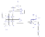
suitable for the ADC. The circuit shown here is for channel 1, but
channel 2 looks identical.
Since the subsequent circuits cannot deal with negative voltage (to keep the circuit simple, the scope has
only a single +5V supply and no negative supply), the only way to measure negative signals is to shift
them up with a programmable offset voltage (between 0 and 4 V) provided by a digital-to-analog converter
(-120V to +200V with a 1:10 probe - but be VERY CAREFUL whenever working with such high voltages!).
The offset is fed in on the bottom of the voltage divider (between C12 - which buffers fast transients - and
R2).
The input divider deserves some further consideration. It is a so-called compensated attenuator and
consists of a combination of a fixed ohmic divider (R1 and R2) and an adjustable capacitive divider (C19
and C6). The reason for adding the capacitive divider is the fact that the protection diodes (D1 and D2) as
well as the input of the op-amp (OP1.1) have some unavoidable parasitic capacitance in the order of a few
pF. With only R1 and R2 this would create a low-pass R-C filter (the divider feeding the parasitic
capacitance which would need some time to charge up), severely limiting the achievable bandwidth.
Quick estimate: output impedance of the divider is R1 || R2 = 187 kOhm, parasitic C_par maybe 20 pF,
that would give a time constant of 187k * 20p = 3.74us and a bandwidth of just 0.35/3.74 = approx. 90
kHz). This is much too low for our scope!
The solution - if you can't beat them, join them. Adding the capacitive divider and adjusting it to the same
division ratio (1:4) as the resistive divider makes the frequency response flat from DC to light (at least in
theory - but close enough for our purpose). The necessary condition is:
(C6 + C_par) / C19 = R1 / R2
Adjustment is done with C19 (see also the end of the assembly guide on the download page). Since
nothing comes for free in life, it's not surprising there is a price to pay - the capacitive divider causes the
scope's input impedance to drop for higher frequencies. Still this is a worthwhile tradeoff and thus such a
compensation can be found in virtually every oscilloscope.
| >> |
| << |

