| aaaaaaaa |

DPScope - Low-Cost USB Oscilloscopes
| |
| |
| |
| |
| | | | |
USB Interface, Power Supply:
uses a USB-to-serial converter cable from FTDI. This cable has a
FT232R chip built into the USB connector and translates the USB
data stream into a standard RS-232 asynchronous serial data
stream (output levels on the serial side are TTL, not true RS-232 -
this is what the microcontroller needs anyway). That way the scope
does not have to deal with a complex USB interface but sends and
receives data as if the connection were a simple RS-232 link.
On the PC side there is a driver that emulates a RS-232 connection as well, so the scope application only
has to deal with a standard serial connection, too. Data transfer rate is still a respectable 500 kBaud (the
converter cable could go up to 1 Mbaud but the transmitted data volume is too small to really need full
bandwidth - each record is approx. 0.5 KByte, so even at 40 frames/sec this amounts to just 20 KByte/sec
or around 200 kBaud average serial data rate (note that each data byte needs a start bit and a stop bit, so
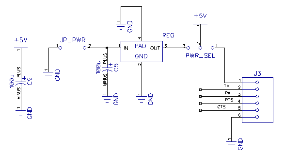
The interface uses software handshaking (the scope responds to each transmission from the PC with an
acknowledge packet), so while CTS and RTS are physically connected - just in case a later revision wants
to use them - they are not used in the current design.
The converter cable also makes the USB port's 5V supply available. The DPScope needs about 250mA of
supply current, a USB port can provide up to 500 mA, so the scope can get its power from the USB line
and does not need an external power supply. One word of caution though, some USB ports have rather
large variation in supply voltage (sometimes down to little more than 4V). In my experience this is mostly
true when connecting to an unpowered USB hub or when many other power-hungry devices are
connected to the same USB hub, so try to avoid this. The latest version of the DPScope software
measures the actual supply voltage and corrects for it (the analog-to-digital converters use the supply
voltage as their reference so any change in the supply directly shows up in the raw date). So while it will
function even at lower voltage, reduced supply voltage reduces the available display range (e.g. at 4V
supply the range is only up to 16V instead of the nominal 20V). Some USB ports (laptops are notorious)
are also quite noisy, this will show up as noise on the measured signals.
If you are absolutely unable to provide close to 5V from USB, or the USB supply turns out to be too noisy,
then the DPScope allows to use an external power supply (7.5V/500mA). All you need to do is add the
regulator (REG, a simple 7805 linear regulator) and a buffer capacitor (C5), hook up the power supply,
and set the jumper (PWR_SEL) to "external supply". REG and C5 are very generic types and should be
available in any hobby electronics store (and in any case are most likely already in your drawer). Note this
is only an option in the kit version of the scope (PCB V1.1) since the assembled version (PCB V1.3) no
longer has space for the regulator (the FT232 USB converter chip took its place).
has to deal with a standard serial connection, too. Data transfer rate is still a respectable 500 kBaud (the
converter cable could go up to 1 Mbaud but the transmitted data volume is too small to really need full
bandwidth - each record is approx. 0.5 KByte, so even at 40 frames/sec this amounts to just 20 KByte/sec
or around 200 kBaud average serial data rate (note that each data byte needs a start bit and a stop bit, so
The interface uses software handshaking (the scope responds to each transmission from the PC with an
acknowledge packet), so while CTS and RTS are physically connected - just in case a later revision wants
to use them - they are not used in the current design.
The converter cable also makes the USB port's 5V supply available. The DPScope needs about 250mA of
supply current, a USB port can provide up to 500 mA, so the scope can get its power from the USB line
and does not need an external power supply. One word of caution though, some USB ports have rather
large variation in supply voltage (sometimes down to little more than 4V). In my experience this is mostly
true when connecting to an unpowered USB hub or when many other power-hungry devices are
connected to the same USB hub, so try to avoid this. The latest version of the DPScope software
measures the actual supply voltage and corrects for it (the analog-to-digital converters use the supply
voltage as their reference so any change in the supply directly shows up in the raw date). So while it will
function even at lower voltage, reduced supply voltage reduces the available display range (e.g. at 4V
supply the range is only up to 16V instead of the nominal 20V). Some USB ports (laptops are notorious)
are also quite noisy, this will show up as noise on the measured signals.
If you are absolutely unable to provide close to 5V from USB, or the USB supply turns out to be too noisy,
then the DPScope allows to use an external power supply (7.5V/500mA). All you need to do is add the
regulator (REG, a simple 7805 linear regulator) and a buffer capacitor (C5), hook up the power supply,
and set the jumper (PWR_SEL) to "external supply". REG and C5 are very generic types and should be
available in any hobby electronics store (and in any case are most likely already in your drawer). Note this
is only an option in the kit version of the scope (PCB V1.1) since the assembled version (PCB V1.3) no
longer has space for the regulator (the FT232 USB converter chip took its place).
| Click image to enlarge |
| >> |
| << |
