| aaaaaaaa |

DPScope - Low-Cost USB Oscilloscopes
| |
| |
| |
| |
| | | | |
Input Stage / Analog Frontend (part 3)
| Click image to enlarge |
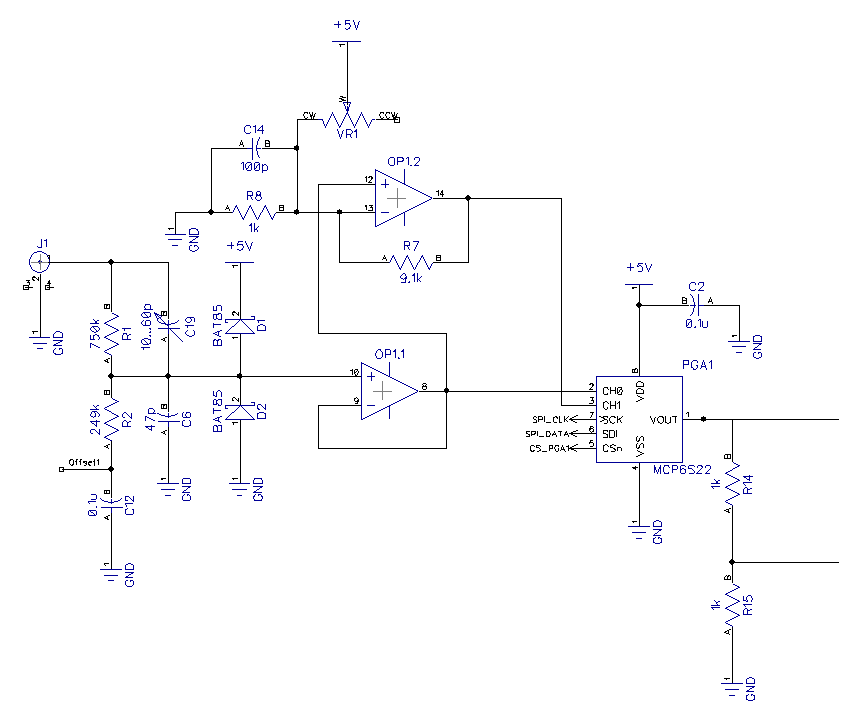
PGA is a beautiful device because it allows us to change the
channel gain (amplification) without any moving parts like relays.
The signal now arrives at the previously mentioned This reduces
cost, component count, size, and improves reliability (no
mechanical wear-out) at the same time. The only reason I can see
aren't many PGAs available for very high bandwidths (several
100 MHz or even GHz). But for the DPScope with it's design goal of 1 MHz or maybe slightly above this is
just what the doctor ordered - the PGA's minimum specified gain is 2 MHz.
Since the two selectable inputs of the PGA are fed with signals differing by a factor of 10, with the PGA we
can effectively choose a total amplification of 1, 2, 5, 10, 20, 50, and 100 only use gain settings 1, 2, 5, and
10.
The microcontroller controls the PGA through a standard SPI interface consisting of three signal lines -
clock, data, and chip select.
The output of the PGA feeds the analog-to-digital converter (ADC) inside the dsPIC microcontroller. It also
drives into a second input which goes to a comparator inside the dsPIC. This comparator creates an
interrupt whenever the input voltage crosses a certain, programmable threshold in a pre-defined direction
(rising or falling signal level, respectively; this is also called a rising - or falling - edge). The threshold
voltage is generated by a 10-bit digital-to-analog converter (DAC) inside the dsPIC (it's amazing how much
peripherals Microchip has put inside a single, inexpensive microcontroller - all this reduces cost and
complexity of the scope a lot). Since the DAC can only produce up to 2.5V (i.e. half the maximum signal
level), the easiest solution was to divide the incoming signal by two with a voltage divider (R14 and R15).
That way the trigger threshold can be set anywhere within the incoming signal range.
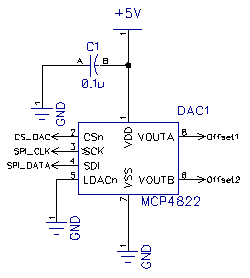
Finally, on the right you see the external 12-bit
digital-to-analog converter (DAC, a Microchip MCP4822)
which sets the offset for the input signal. It has two
independent output channels, one used for each of the
two scope input channels. The microcontroller drives the
DAC through the SPI interface as well (the dsPIC uses the
chip selecty (CS) line of the respective device - DAC, PGA1
or PGA2 - to determine which device is getting the SPI
| >> |
| << |
